Go behind the scenes of our interactive homepage hero
Raymarch, Don't Walk
Here at y'all, we are built differently, both in our words and in our work. So it's only fitting that the hero of our homepage should literally reflect this 🥁. So we built, from scratch, a fun interactive 3d composition that combines a pair of modern techniques in a unique way, to create not just a clear, glass-like orb, but one that morphs and squiggles as you touch it with your mouse. Also just like us? Ahem.
This blobby gel-y goodness is achieved through a 3D technique known as raymarching. The reflections and distortions caused by the blob, similar to what you'd see looking through an old windowpane or a glass bottle, are known as refraction, which are achieved with a shader. But why, you may ask, did we put these two together? Well, firstly because we believe in learning through experimentation here at y'all labs. But secondly, because we can.
Warning: the below content is technical, but we will try to make it understandable. You can leave that graphing calculator at home.
Who is Ray and why does he March
Look at some object, any object, in the distance. Now imagine an arrow beaming from your eyes to that object. That arrow is a "ray."
You likely only have two eyes, but now imagine that every pixel on your monitor is an "eye" of sorts, looking straight behind it into a 3d scene. Each of those eyes beams out (emits) an arrow (ray) that travels (marches) farther and farther on until it collides with an object, and tells us what the thing it hit looks like. Your monitor puts those all together in a grid to form the image you see above.
So for each pixel in our image, we'll have one ray.

The rays will march along our scene until they hit upon an object. How does it known when it's hit an object? Unlike a typical 3d scene where we place objects in a field and can say "there is a box exactly 3 feet from the camera and a 1 foot to the left," with this technique we have to shape and place our objects using math. 😱
To do that we use something called a Signed Distance Field (SDF). This is a mathematical function that describes the shape of a 3d object (box, sphere, etc.) It returns a positive value if the ray lands outside of an object or negative if it lands inside. So returning to our monitor, we send out a ray from each pixel, and if the SDF for that pixel returns a value less than or equal to 0, then bingo, we have a collision, and we know that pixel will show something. But what?
(Shout out to this great article by Inigo Quilez, which helped us in developing our own unique shapes.)
Shading and Refraction
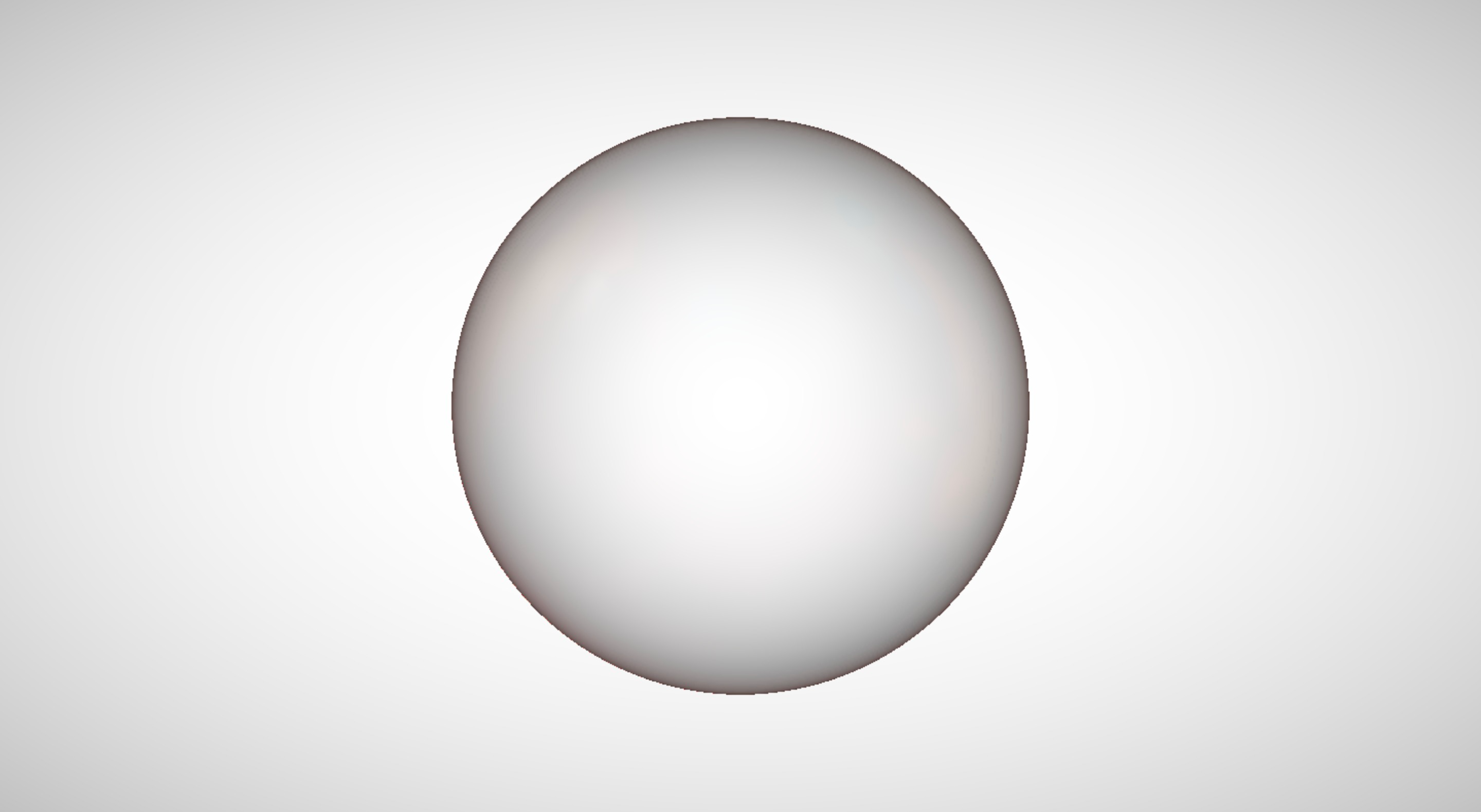
Once the raymarcher tells us we've hit something, we know that the pixel should show our object. As a simple example, let's suppose we're using an SDF that generates a sphere, where a hit means we shade that pixel white and all else is black. Then we'd have something like this:
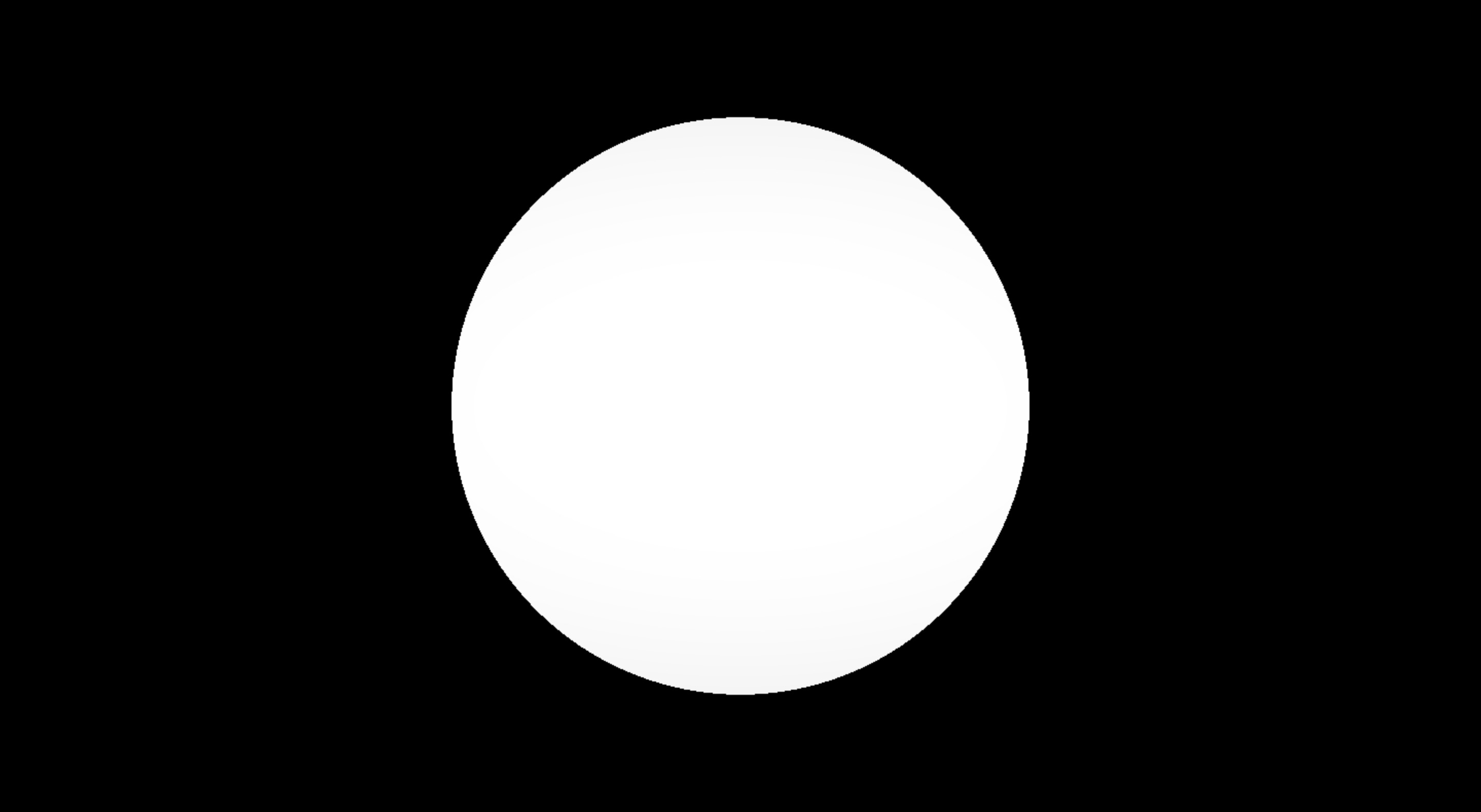
Just a boring circle with zero depth to it. To add dimensionality, we need to add a lighting model to it, to simulate how light interacts with a sphere IRL.
Image Based Lighting
There are many different lighting models under the sun that can help us bring the sphere to life. But one of the easier models that we can use is an "image based" approach.
Image Based Lighting (IBL) is a 3D graphics technique that helps make scenes look realistic by using images to capture the surrounding environment's lighting and colors. Think of it like bringing a shiny glass ball into a room with colorful walls; the ball will reflect the colors around it, blending naturally with its surroundings. In IBL, we make those "walls" out of images, so when an object like our sphere is placed in this digital environment, it interacts with the light and colors from these images, creating realistic reflections, shadows, and illumination.
This series of images is called a cubemap and you can think of it like a six sided cube that surrounds our scene:
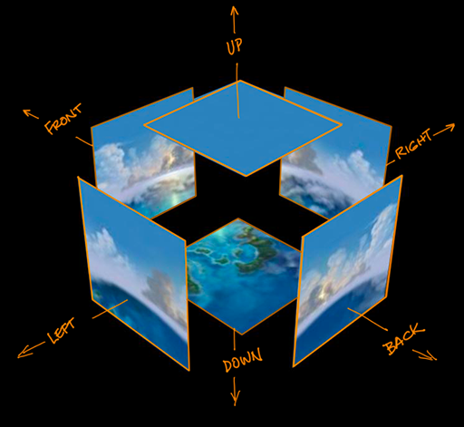
When a ray hits our object and reflects off it, we can use that resulting direction as a value hitting our surrounding cubemap. A completely reflective object like a mirror will be a clear or blurred copy of the surrounding cubemap depending on the "roughness" of the surface like so:
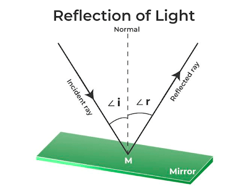
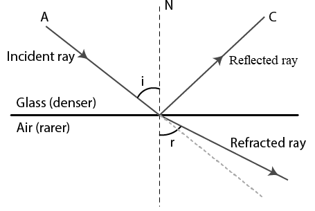
We use a programming language called GLSL to help create these reflections. First, you find out how light interacts with the object's surface at the point it hits, using a "normal," which is a line standing straight up from the surface at that point, much like a stick standing upright on a flat table. By knowing this normal and the direction from which the light comes (the "incident ray"), you can figure out how the light will bounce off or pass through the object, creating a glass-like look and distorting the view of objects around it.
Refraction
However like mentioned before, and as you've no doubt noticed in real life, glass is not completely reflective. Most light will pass through the surface (refract), but some will reflect back to you based on the angle of the light (incident ray). This is what's known as the Fresnel effect. Very simply, it is the observation that amount of reflection you see on a surface depends on the viewing angle.
Whereas in real life the Fresnel is dependent upon types of materials and light sources, in computer graphics, we can customize this to our desired effect. Here, we wanted the sides of our glass to reflect our cubemap more strongly while the interior of the sphere will refract through the object, resulting in a defined edge and clear-ish center:
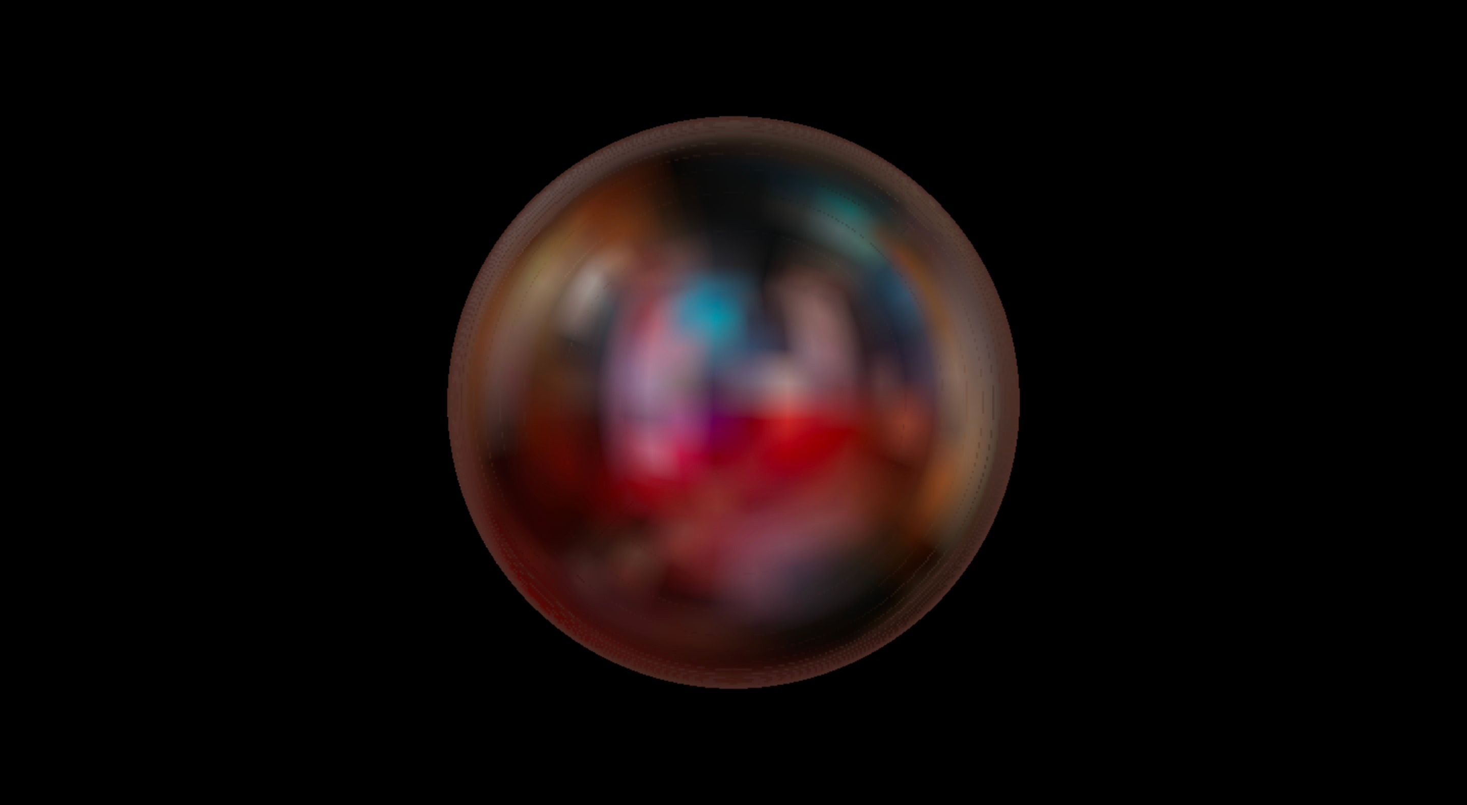
In the physical world, materials have an Index of Refraction (IOR), which measures the behavior of light as it passes from objects of differing densities. Luckily, the language we are building this in (GLSL), has a built-in refraction function that does the heavy lifting for us given a virtual IOR value. For glass, the IOR is around 1.52. That gives us this result:
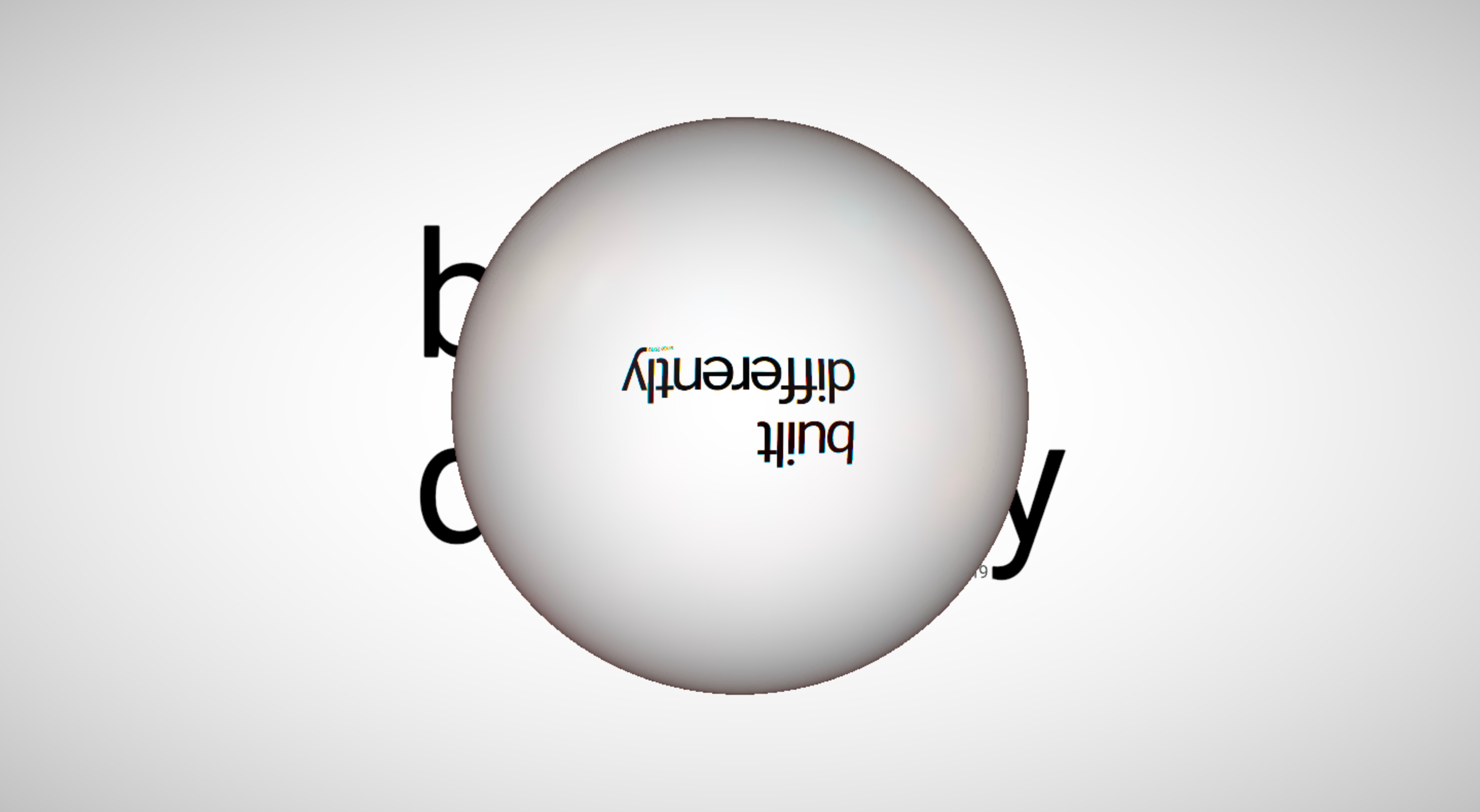
Our background text is essentially static. Thus, we can treat the background text as an image and use the same idea as our IBL cubemap as described previously. Notice how the image is actually flipped, just like a real world glass sphere!
Chromatic aberration
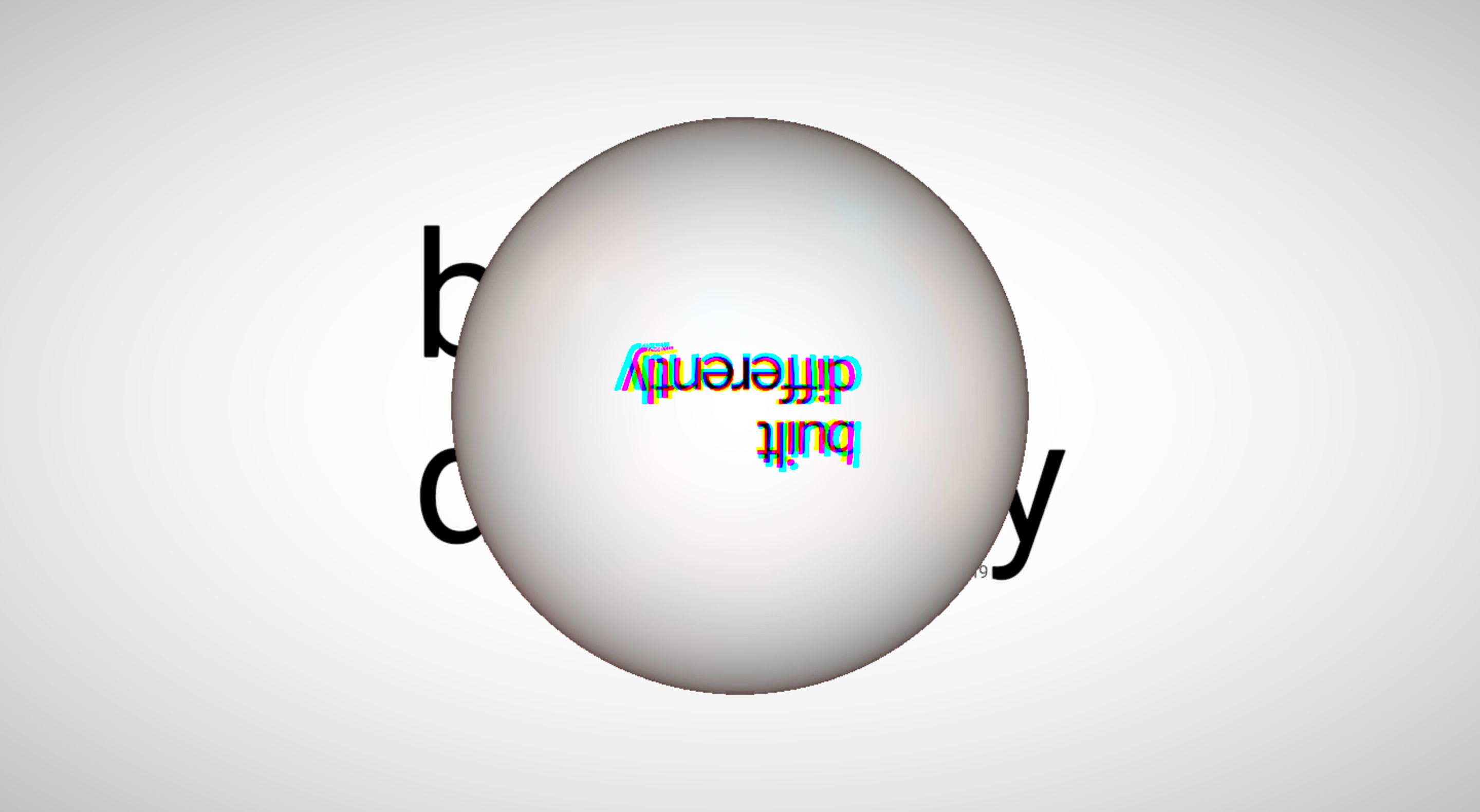
The one thing that is missing now is the chromatic aberration that happens with glass, where the different wavelengths of light are refracted differently creating an amazing dance of color. While with modern clear glass this is so subtle as to be unnoticeable, you can see this effect more strongly on older leaded glass windows, which act like a kind of prism, separating the different wavelengths of light.
We can achieve the same effect by simply offsetting the IOR values slightly for each color channel of red, green and blue. This means calculating a different refraction direction for each color and adding them back together to create our image like so:
There we have it folks!
In it's basic form, this is how we achieved the look of our site's hero. Through the magic of raymarching and a little technical shading work we were able to create a performant and interactive experience for the web. We customized the glass IOR, fresnel, and chromatic aberration values to make something more fantastic than realistic, but we hope these comparisons to real-world phenomena have given you an idea about what went on behind the scenes here.
For more detail on these concepts (and you thought this was technical!) check out these links, which helped us in developing this article: